Preparation
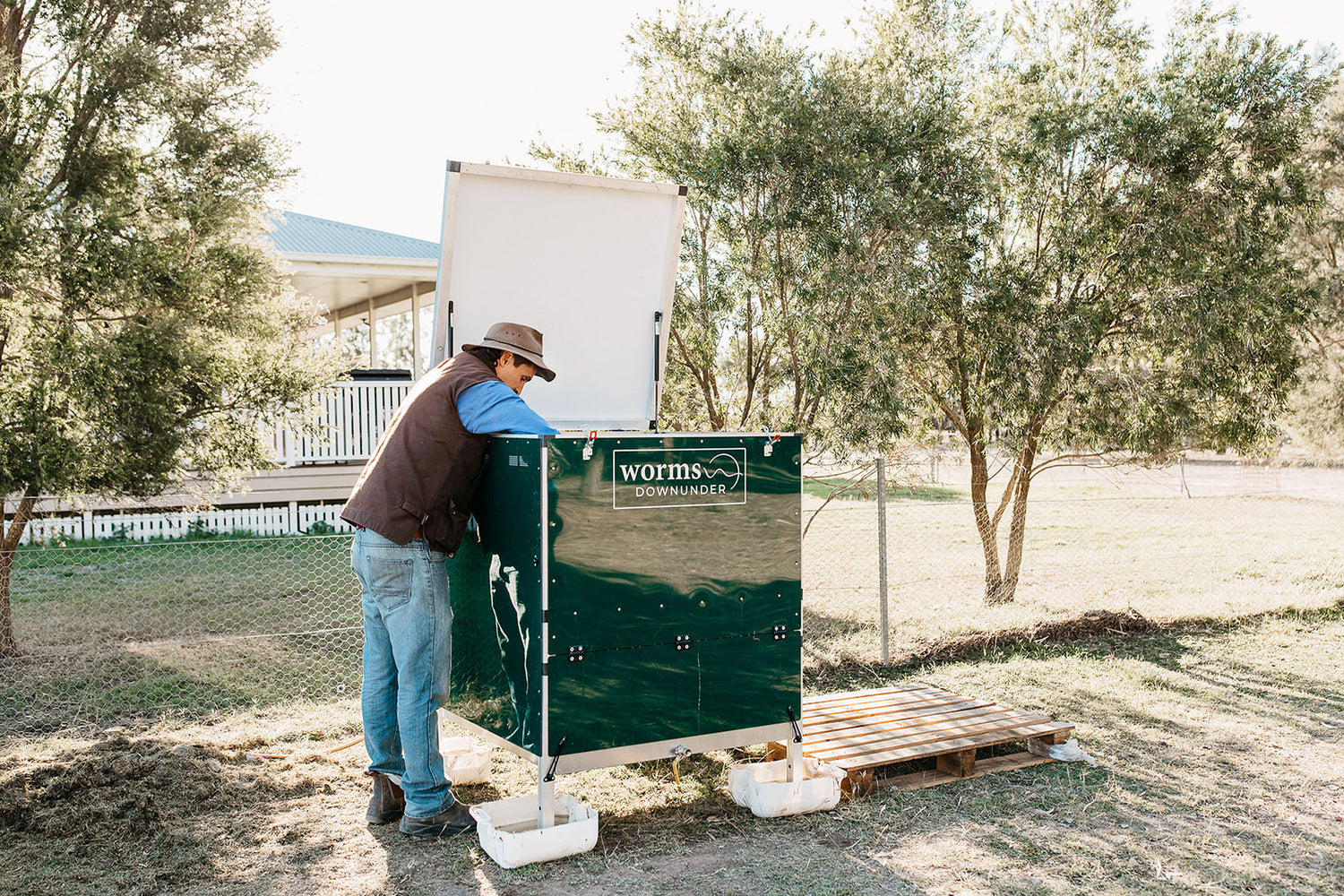
Select a location where the worm farm is shaded from full sun and protected from the west. Ensure the ground is level and firm before beginning assembly.
Tools Required
- Stanley knife
- Rubber mallet
- M6 Allen key
- 10mm spanner
- 12mm spanner
- Impact driver/drill or screwdriver with Phillips head bit
Box 1: Frame Assembly
Contents
Parts:
- 2x Side sub-assemblies
- 1x 1004p tube
- 3x 10¹⁰p tubes
- 16x Joiner hole plugs
- 2x Angle plates (to be assembled later)
Hardware:
Tools to Use:
Frame Assembly
Locate and identify parts:
- Find the 1004p tube (numbers are laser-etched onto parts).
- Determine the front of the worm farm by locating the pre-assembled buttons.
Assemble 1004p tube:
- Position it at the back of the worm farm with small holes facing outward (not upwards or downwards) Note: The panels will be assembled onto the frame via these holes.
- Tap into place using a rubber mallet.
Install 1010p panels:
- Attach them to the remaining joiners, ensuring holes face outward.
Attach the second side sub-assembly:
- Align with the joiners and use a rubber mallet to secure them.
TIP: Start all joiners with the mallet before making a second pass to ensure a firm connection.
Stand the worm farm upright.
Insert joiner hole plugs:
- Locate 16x joiner hole plugs and install them in the following locations:
- Internal face: Top, middle, and bottom of each leg.
- External face: Bottom hole.
For single-unit assembly: Insert joiner hole buttons.
Retrieve Box 3 and remove the Fastener and Accessories box.
Adjustable Feet Assembly
- Locate feet and tube inserts.
- Thread feet into tube insert until flush.
- Use a rubber mallet to tap the foot into the leg.
- Note: The threaded feet allow for height adjustments to level the worm farm. Adjust feet height after assembly is complete and the farm is in its final location.
Box 2: Scraper System & Leachate Tank Assembly
Contents
Parts:
- 1x Scraper system frame
- 2x Scraper system blades
- 1x Leachate tank
- 11x Bedding angles
- 2x Worm cast trays (to be installed later)
Hardware (Located in Box 3):
- 1x Leachate tank hardware bag
- 1x Scraper system hardware bag
- 1x Plate hardware bag
Tools to Use:
Leachate Tank Assembly
- Pre-assemble split washers and regular washers onto 16x M4 x 10mm screws.
- Slide the leachate tank into position, ensuring the hole is at the front.
- Secure with screws in the four corners first, then install the remaining screws.
Scraper System Assembly
- Pre-assemble split washers and flat washers onto screws.
- Secure scraper blades to the scraper system frame with screws at both ends first.
- Install remaining screws.
- Slide the scraper system onto plastic angles.
- Ensure the round bar handle is at the front of the worm farm.
Angle Plate Assembly
- Retrieve angle plates from Box 1 and locate the Plate Hardware bag (16x M4 x 16mm screws).
- Align plates at the back of the worm farm and secure with screws.
- TIP: Pull the scraper system forward to stabilize the plate.
- Repeat fastening on the front plate.
- Install 11x bedding angles into plates.
Box 3: Lid & Panel Assembly
Contents
Parts:
- 1x Front panel sub-assembly
- 1x Lid sub-assembly
- 1x Back panel
- Fasteners and Accessories box
Hardware:
- Panel hardware bag
- Hinge hardware bag
Tools to Use:
Lid Assembly
- Attach hinges: Thread M6 x 45mm bolts into hinge before assembling onto the 1004p panel (back of worm farm).
- Secure using M6 washers and nyloc nuts (finger-tight).
- Tighten nyloc nuts with a spanner.
- Install lid: Place it on top with lockable latch hooks at the front.
- Assemble M6 bolts, washers, and nyloc nuts.
- Peel off protective film from the lid panel.
Back & Front Panel Assembly
- Attach the back panel using pre-assembled washers and screws, ensuring the gasket contacts the aluminum frame.
- Hang the front panel on lockable latch hooks before securing it with screws.
Box 4: Side Panel & Final Assembly
Contents
Parts:
Hardware:
Tools to Use:
Side Panel Assembly
- Remove the protective film.
- Install screws into the top corners first, followed by bottom corners.
- Secure the remaining screws and tighten.
- Install gas struts: Use a 12mm spanner to fasten struts into designated holes (thicker tube attaches to lid, thinner tube attaches to frame).
Additional Components
- Misting Head: Insert through panel and screw hose connection onto the misting head thread.
- Leachate Tap: Assemble rubber washers and secure through the tank hole. Tighten the lock nut and remove the bung.
- Worm Cast Trays: Slide trays into slots with finger holes facing the front.
Final Steps
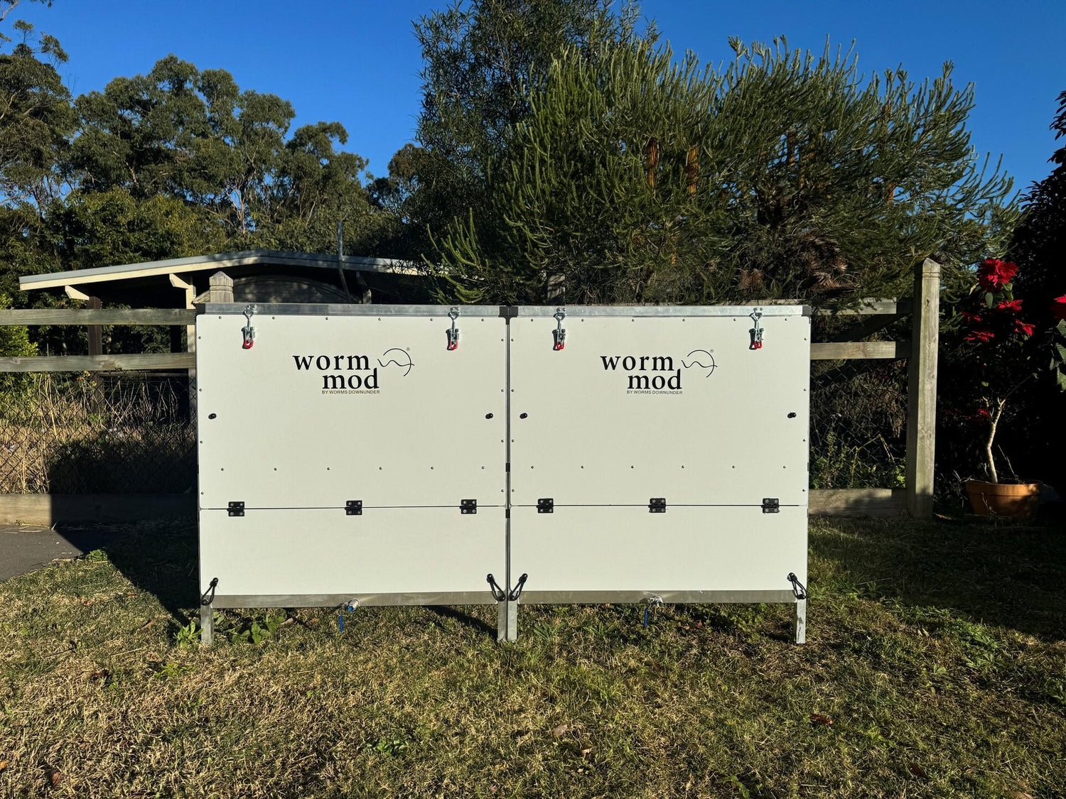
- Single Unit: Move to final location and level using adjustable feet.
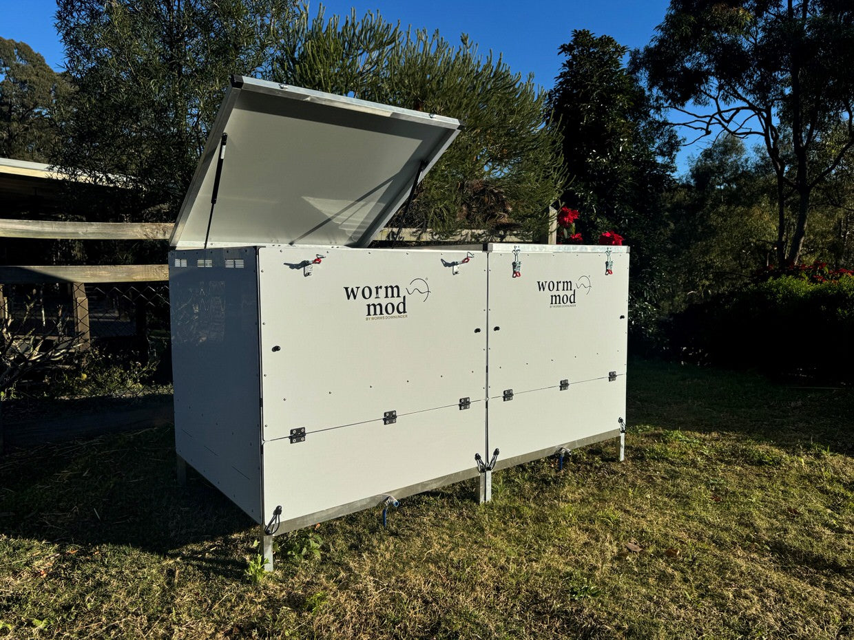
- Multiple Units: Follow the video guide to join additional units.
- Lid Alignment: Adjust feet if the lid does not sit squarely.